Just wonder if an option could be in the menu

Where the axes could be selected rather then the default blue up.

Where this has come up is a bird house front that has vents that will be cut on the vertical workstation and then the hole that is cut in the front. To do this I’m making a copy of the part then making it unique and changing the axes to run the plug-in a second time. Doing so works but then if I want to make changes I have to do it to two parts.

This is the first I’ve run into this and maybe there is a better solution?

Ed

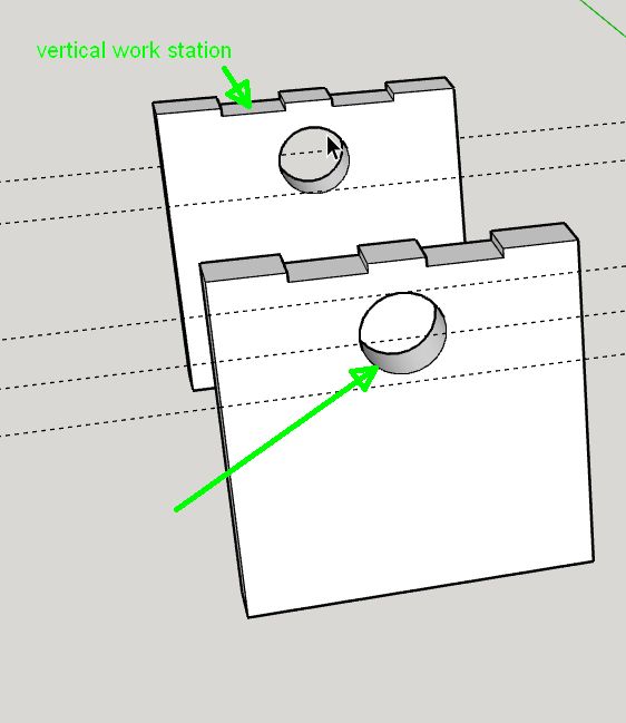
Hmmm… that’s a good one!

So here’s what you could do… You could make the part, and make it a component. Then copy it. Whatever edit you do to one component will happen to another component. Right before you go to make the part, right click the one you need to change the axes on and select “Make Unique”. Then right click it again and select “Change Axes”.

This way you can edit both at the same time right up until the moment you go to make something. Once you make it unique the link between the two components will be broken…

What you could also do is NOT make the second one unique. You could double click on the component who’s axes you want to rotate. Once you double click on it, hit CTRL A to select all of the bits that make up that component.

Press ESCAPE, or click outside of the component to get out of the context of that component. They hit “CTRL V” (paste)

That’ll paste the geometry there and you can make a component if it and change the axes to whatever you want.

I know neither of these scenarios are ideal for exactly what you want, but perhaps it’ll make the workflow a little easier on a more complex assembly.

This is definitely a good reason to look at multiple axes per part…

I had a similar issue with an Adirondack chair project I’m working on. The chair legs have joinery to be cut with Origin on 3 different faces, requiring 3 separate components or 3 “change axis” moves. Not sure what a fix would look like, but something to streamline the workflow would be very helpful

Do you have a drawing that you’d be willing to post? That might be really helpful in figuring this out…

Jim’s Adirondack Chair w: joinery2 less photo.skp (1.7 MB)
This is the Sketchup file for the chair I’m working on.

Glenn

That’s a really great drawing!

So here’s a question:

For the original workflow we set it so that the orientation of the axis dictated the direction of cut. It’s not the most obvious workflow but I think once you understand it, it makes sense.

This obviously doesn’t work when you want to cut on multiple sides of a part… So my above suggestion is a good workflow to cut this NOW.

But, going forward what if we let users select faces that indicate the top of cut… So on some of those chair parts you could select two (or more) faces and it would lay those out flat as if they were the top of the cut… What do you think?

Eric, thanks for taking a look. I will try your suggested workflow on my next piece and let you know how that works. Going forward, selecting faces on a component would be helpful, in fact the Face SVG plugin written by Marvin Greenberg allows you to do just this. The challenge from my perspective is to layout the faces in the SVG file in such a way as to allow me to accurately position each of the faces on my workpiece using the onboard grid, anchor and rotation tools. Thanks for your help and for your work on this plugin

Glenn

One of the goals with this plugin is “What you see is what you get” IE I want people to think, and design in 3D. I don’t want them to have to go back to 2D.

To that end, I think the going from 3D to 2D in SketchUp isn’t the best workflow… You end up with two sets of objects… I’d rather people have their 3D objects in context so they can see how stuff fits together.

This is a challenge when you’re machining multiple sides of a part, especially with the Shaper that essentially forces you to go back to 2D to get your cut files on tool…

I think there’s a way to do this so that it makes sense… I’m thinking letting people pick faces/planes to machine from is the way to go. It’ll be a little while until we can build that however…

I fully agree. I like the way the Fabber plugin takes a component selection directly to the SVG file. My only concern as stated above, is having the layout of parts in the SVG file done such that each of them can be accurately located on a workpiece for cutting on Origin. For example, if I currently select 3 components from my model and use the plugin to generate an SVG, they will be oriented in a line, one after another. Placing and cutting the first and last of these should be easily achievable by using anchor points on either end of the SVG layout. The component that is in the middle however, I believe would be more difficult to place on the workpiece accurately, since none of the anchor points would relate to a know point on the component. I hope that makes sense. Another approach might be that if I select 3 faces from a component, the plugin would generated 3 separate SVG files.

That totally makes sense.

Here’s a way that you could accomplish what you want right now… We only export what you select, so if you want to place those parts accurately on Origin, you can select a part and just export that part. You could do this for the same part twice, rotating the axis between each export. That way you’d get two “views” of that part, and you’d be able to place them accurately with the grid tool as they’d come in as separate SVG files. Make sense?

Now, for the future what do you think about something like this:

You’d design you parts as normal, then you’d be able to pick which faces you want to export, and it could be more than 1 for each part.

You do your export and you’d get two (or more) rows of parts that represent each face you’ve exported…

That is exactly what I am finding in developing efficient workflows. While it is nice to just select the complete model and see all the parts layed out, components can have different thicknesses or be made of different wood/material or have more than one face to cut. Generating multiple SVGs is a great way to handle this as long as you correctly label each one to keep things straight.

That sounds like it would be a good solution. Look forward to the continued improvements. Thanks again for all the efforts.

Glenn